Installation, Testing & Preventive Maintenance
Power equipment is built to last 30 to 40 years — but only if it’s received correctly, installed properly, and maintained on a real schedule. This guide collects the field practices our service team uses across hundreds of sites.
1. Receiving and Pre-Installation Inspection
The clock starts ticking on equipment health the moment it leaves the factory. The most common — and most preventable — failures we see in the first year trace back to receiving issues that weren’t caught.
What to check the day it arrives:
- Impact recorder — most large transformers and switchgear ship with a 3-axis impact recorder. Read it before signing the bill of lading. Anything over 3g warrants an inspection report.
- Visible damage — bent fins, dented enclosures, cracked bushings, scuffed paint. Photograph everything before unloading.
- Oil level and pressure (for liquid-filled units) — gauge should read positive at ambient. A negative reading suggests a leak.
- Nitrogen blanket (for sealed liquid-filled) — should read 1–3 psig at 25 °C. Anything below ambient is a red flag.
- Loose hardware inside enclosures — hex on every torqued connection per the equipment’s torque chart.
Carriers’ liability ends 24–48 hours after delivery. If shipping damage isn’t documented in that window, the cost falls on the project. A 30-minute inspection has saved customers six-figure repair bills.
2. Storage Before Installation
Equipment that sits on a job site for weeks or months before energization has special storage requirements:
- Indoors and dry wherever possible. If outdoor storage is unavoidable, use waterproof tarps with airflow underneath to prevent condensation pooling.
- Energize space heaters (most MV switchgear and dry-type transformers have them). They prevent moisture from condensing inside the enclosure during temperature swings.
- Inspect monthly if storage exceeds 30 days — check for moisture, pest intrusion, and corrosion.
- Keep the original packaging on bushings and other shipped-loose components until installation day.
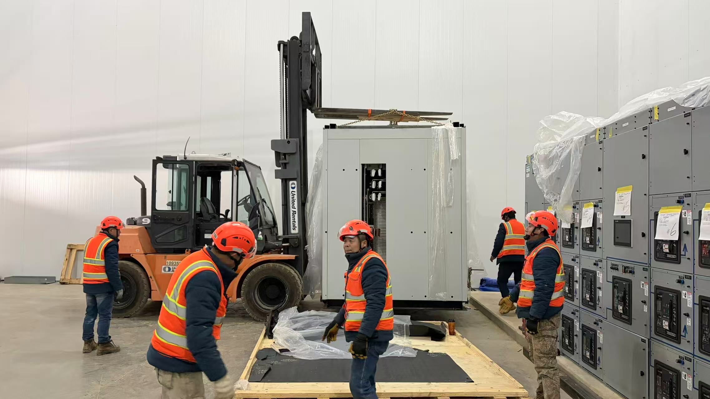
3. Installation Best Practices
Foundation and Anchoring
For pad-mounted transformers and free-standing switchgear, the concrete pad needs to be:
- Level within ±¼” across the equipment footprint (more critical for liquid-filled units, where uneven mounting affects oil flow).
- Sized with a minimum 6″ overhang on all sides per IEEE.
- Anchored per the manufacturer’s drawings — usually ½” or ⅝” expansion or epoxy anchors at the corners.
Cable Termination
The single most common cause of in-service failures we investigate is poor cable termination. Watch for:
- Stress cone preparation on MV cables — clean, square cuts, no nicks in the insulation, semicon removed cleanly without scoring the dielectric.
- Compression lug crimps — use the correct die for the lug, full crimps, and don’t reuse a lug after a failed crimp.
- Torque every bolted connection with a calibrated wrench. Re-torque after the first heating/cooling cycle.
- Heat-shrink or cold-shrink terminations applied per the kit instructions — temperature, sealing tape, ground braid all matter.
Grounding
System and equipment grounding is non-negotiable. Confirm:
- Equipment ground to the building grounding electrode system per NEC Article 250.
- Ground resistance < 5 ohms (target < 1 ohm for substations and critical facilities).
- All bonding jumpers on bushings, tank, and enclosure are torqued and continuous.
4. Pre-Energization Testing (Commissioning)
Never energize new equipment without commissioning testing — and never accept “the factory tested it” as a substitute for field testing. Recommended tests, drawn from NETA ATS-2023:
For Transformers
- Insulation resistance (Megger) — minimum 1 minute, ideally 10 minutes, with PI calculation. Acceptance: PI ≥ 2.0 for liquid-filled, ≥ 1.5 for dry-type.
- Turns ratio test (TTR) on every tap position — should be within 0.5% of nameplate.
- Winding resistance — compared to factory test report.
- Power factor / dissipation factor — for units > 500 kVA, baseline reading at commissioning becomes the reference for future trending.
- Oil dielectric strength (liquid-filled) — minimum 30 kV per ASTM D877.
- Dissolved gas analysis (DGA) — baseline sample, then again after 30 days of operation.
For Switchgear
- Hi-pot test per IEEE C37.20.2 (75% of factory test voltage for field).
- Insulation resistance phase-to-ground and phase-to-phase, all breakers in test position.
- Contact resistance across each breaker pole — typically < 200 µΩ.
- Mechanical operation — close, trip, charge mechanism, all at rated and minimum control voltage.
- Protective relay testing — secondary injection on every relay.
- CT polarity and ratio — confirm all current transformers are wired correctly.
A full NETA-acceptance test on a 1500 kVA transformer is roughly $2,000–3,500. The cost of an in-service winding failure is 50–100x that, before counting business interruption.
5. Preventive Maintenance Schedule
The right maintenance interval depends on environment, criticality, and equipment type. As a starting point:
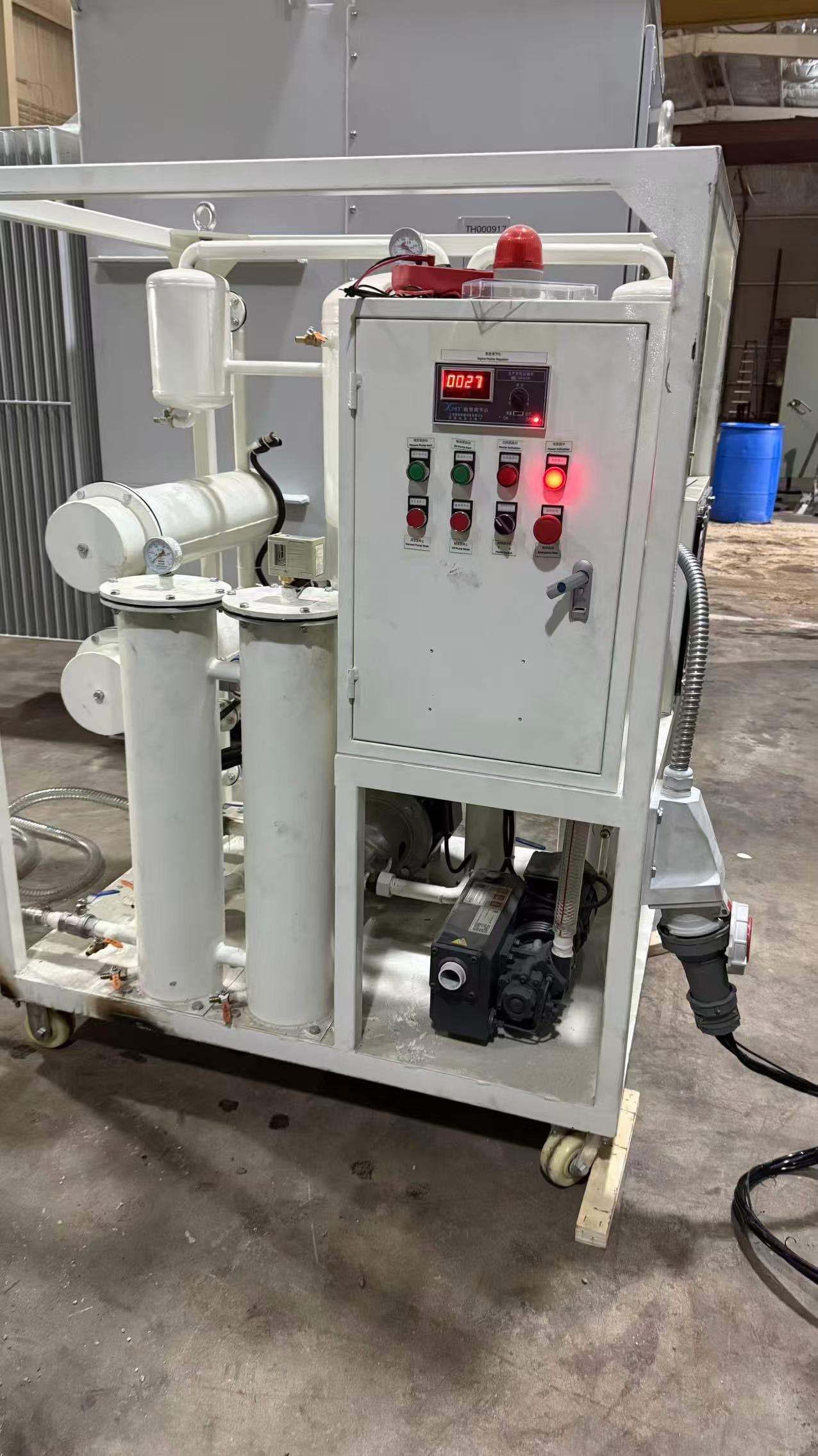
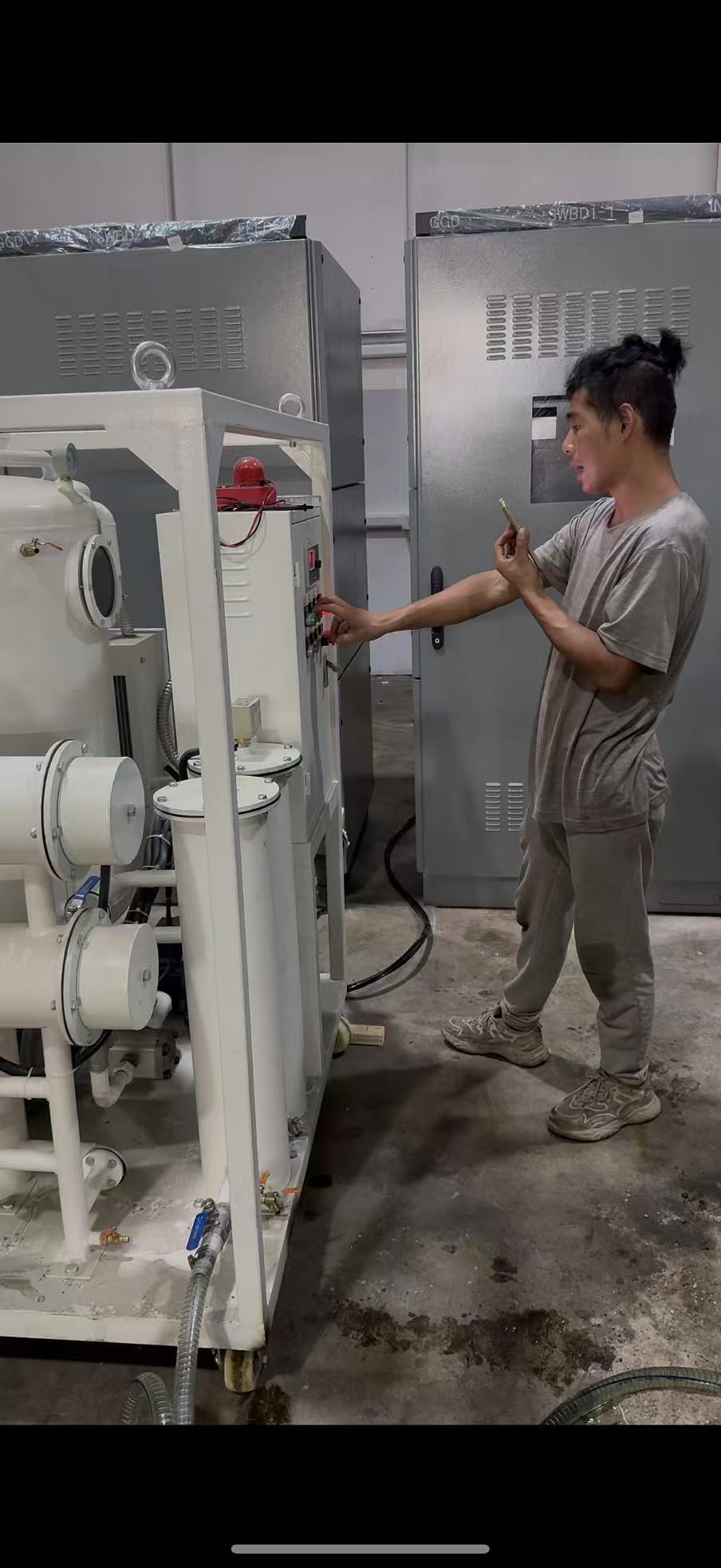
6. Oil Management for Liquid-Filled Transformers
Oil does three jobs in a transformer: insulate, cool, and quench arcs. All three degrade as oil ages. The two enemies are moisture and contamination.
- Sample annually for dissolved gas analysis (DGA) and oil quality.
- Track key gases — hydrogen, methane, ethylene, acetylene. Acetylene > 5 ppm is a serious flag for arcing inside the tank.
- Filter and dehydrate when moisture exceeds 35 ppm at operating temperature, or dielectric drops below 25 kV.
- Don’t reuse contaminated oil — even after filtration, severely degraded oil should be replaced or reclaimed.
7. Common Failure Modes
- Loose connections → caught by annual thermography. A 5 °C rise on a connection that was clean last year means it’s loosening.
- Moisture ingress → caught by Megger trend, oil DGA (high H₂ + CO), and visible corrosion at gaskets.
- Insulation degradation → caught by power factor trending. A jump > 0.5% from baseline warrants investigation.
- Animal intrusion → install pest screens on every vent.
- Bushing failure → caught by power factor and capacitance testing.
8. Documentation
For each piece of equipment, maintain:
- Original factory test report and shipping records.
- Commissioning test report — these are the baseline for everything that follows.
- Annual and triennial maintenance reports, sortable by asset.
- DGA history charts for oil-filled units.
- Protective relay settings file and any changes (with the coordination study they came from).
- Spare parts inventory linked to the asset.
XENERPOWER offers full-service maintenance contracts for transformer and switchgear fleets — annual visits, NETA testing, oil analysis, and emergency response.
Need a Maintenance Plan?
From a one-off NETA acceptance test to a fleet-wide service contract — our field team can help.